
MATERIAL
- NBR (Nitrile)
- PTFE (Polytetrafluoro Ethylene)
- HNBR (Hydrogenated NBR)
- ACM (Polyacrylate)
- EPDM (Ethylene Propylene Diene)
- PU (Polyurethane)
- VMQ (Silicone)
- CR (Chloroprene Rubber)
- FKM (Fluorocarbon)
- SBR (Styrene Butadiene Rubber)
STANDARD
- JIS
- ASTM
- DIN
- BS
- SAE
SIZE
- Metric
- Inch
EQUIPMENTS
- For material research: tensile testers, hardness testers, oscillating disc Rheometers, etc.
- For design and R&D: scal life testers, radial load testers, etc.
- For production: automatic CNC lathes, rubber compound kneaders, rubber cutters, rubber slicers, low temperature storage, sanding machines, bonding machines, rubber compression molding machines, trimming machines, etc.
- For QC: Micro-Vu, hardness testers, etc.
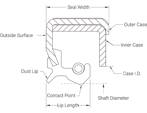
OIL SEAL CHARACTERISTICS
 TC Type
 TA Type
Seal I.D. Tolerance Chart - Inch
| SHAFT | I.D. | Tolerance | Spring loaded | Tolerance |
|---|---|---|---|---|
| up to 0.500 | -0.027 | +0.004/-0.008 | -0.039 | ±0.008 |
| 0.501~1.000 | -0.032 | -0.044 | ||
| 1.001~2.000 | -0.035 | +0.006/-0.012 | -0.053 | ±0.012 |
| 2.001~3.000 | -0.040 | -0.060 | ||
| 3.001~4.000 | -0.048 | -0.068 | ||
| 4.001~6.000 | -0.056 | -0.076 | ||
| 6.001~10.000 | -0.062 | +0.008/-0.016 | -0.086 | ±0.016 |
| 10.001~13.000 | -0.070 | -0.094 | ||
| 13.001~16.000 | -0.078 | -0.102 | ||
| 16.001~20.000 | -0.086 | -0.110 | ||
| 20.001~40.000 | -0.120 | +0.010/-0.020 | -0.157 | ±0.020 |
| 40.001~ | -0.140 | +0.012/-0.020 | -0.178 | ±0.024 |
Seal O.D. Tolerances Chart – Inch
| Bore Diameter | Metal case | Tolerance | Rubber covered case | Tolerance | G type | Tolerance |
|---|---|---|---|---|---|---|
| up to 1.000 | +0.004 | ±0.002 | +0.006 | ±0.003 | +0.010 | ±0.003 |
| 1.001~2.000 | +0.007 | +0.012 | ±0.004 | |||
| 2.001~3.000 | +0.008 | +0.014 | ||||
| 3.001~4.000 | +0.005 | +0.010 | ±0.004 | +0.016 | ||
| 4.001~6.000 | +0.003/-0.002 | +0.012 | +0.016 | +0.006/-0.004 | ||
| 6.001~8.000 | +0.006 | +0.018 | ||||
| 8.001~10.000 | +0.008 | +0.004/-0.002 | +0.014 | +0.020 | ||
| 10.001~20.000 | +0.006/-0.002 | +0.016 | ±0.005 | +0.022 | +0.008/-0.004 | |
| 20.001~40.000 | +0.008/-0.002 | +0.018 | ±0.006 | +0.024 | ||
| 40.001~60.000 | +0.010/-0.002 | +0.020 | ±0.007 | +0.026 | +0.010/-0.004 |
Seal Width Tolerances Chart – Inch
| Width | Tolerance |
|---|---|
| All width | +0.015/-0.015 |
Seal I.D. Tolerance Chart - Metric
| SHAFT | I.D. | Tolerance | Spring loaded | Tolerance |
|---|---|---|---|---|
| <10.00 | -0.60 | +0.10/-0.20 | -0.90 | ±0.20 |
| 10.01~18.00 | -0.70 | -1.00 | ||
| 18.01~30.00 | -0.80 | -1.10 | ||
| 30.01~50.00 | -0.90 | +0.15/-0.30 | -1.40 | ±0.30 |
| 50.01~80.00 | -1.10 | -1.60 | ||
| 80.01~120.00 | -1.30 | -1.80 | ||
| 120.01~180.00 | -1.50 | -2.00 | ||
| 180.01~250.00 | -1.60 | +0.20/-0.40 | -2.20 | ±0.40 |
| 250.01~300.00 | -1.80 | -2.40 | ||
| 300.01~400.00 | -2.00 | -2.60 | ||
| 400.01~500.00 | -2.20 | -2.80 |
Seal O.D. Tolerances Chart – Metric
| Bore Diameter |
Metal case Tolerance |
Rubber covered case Tolerance |
G type Tolerance |
|---|---|---|---|
| <10.00 | +0.20/+0.10 | +0.30/+0.15 | +0.40/+0.20 |
| 10.01~18.00 | |||
| 18.01~30.00 | |||
| 30.01~50.00 | |||
| 50.01~80.00 | +0.23/+0.13 | +0.35/+0.20 | +0.45/+0.25 |
| 80.01~120.00 | +0.25/+0.15 | +0.50/+0.30 | |
| 120.01~180.00 | +0.28/+0.18 | +0.45/+0.25 | +0.55/+0.35 |
| 180.01~250.00 | +0.30/+0.20 | +0.70/+0.40 | |
| 250.01~300.00 | |||
| 300.01~400.00 | +0.35/+0.23 | +0.55/+0.30 | +0.75/+0.45 |
| 400.01~500.00 |
Seal Width Tolerances Chart – Metric
| Width | Tolerance |
|---|---|
| <10.00 | +/-0.20 |
| 10.00 | +/-0.30 |
HYDRODYNAMIC FEATURES - HELIX DESIGNS
The helix can improve the performance of sealing lip by pushing the medium back into the fluid reservoir.
The helix applies to all rotary seals. There are three types available: Bi-directional (W Type) and Single direction (R Type and L Type):
The helix applies to all rotary seals. There are three types available: Bi-directional (W Type) and Single direction (R Type and L Type):
W Type


L Type


R Type


